The RS-232 protocol
Skills:
ML Maths Basics80%
Key Takeaways
The video explores the RS-232 protocol, covering its electrical and timing characteristics, and demonstrates how to implement a serial interface using a 6502 processor and assembly language programming. The RS-232 protocol is used for serial communication, and the video discusses its use of negative voltage to represent a binary one and positive voltage to represent a binary zero, as well as its clock synchronization and start bit mechanisms.
Full Transcript
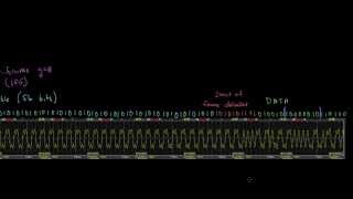
a while ago I built this little breadboard computer and now I want to connect an rs-232 serial interface to it and these serial interfaces used to be ubiquitous on computers for connecting to modems and printers and mice and whatnot but nowadays everything's USB and you typically need a USB adapter like this if you want an rs232 Port but there still tend to be Niche devices that use the serial interface like this router that has a console Port this is actually a Serial interface and with the right adapter we can connect this to a computer and use a Serial terminal program to log in configure and troubleshoot this router using a basic text interface and that's what I want to add to my breadboard computer a serial connection that I can use to create a basic text interface like this it's called rs-232 because it was originally recommended standard 232 back when it was introduced in 1960 and that's still often how it's referred to and I'll often call it that but it's now officially called tia232 and if you want to read the actual standard you can get your very own copy for just 156 dollars here's my copy and as it turns out much of what's in here isn't relevant to any modern or even any really widespread historical implementation of rs-232 for example you know the standard requires this 25 pin connector and while 25 pin connector was common at one point even then most of the pins were unused but the ti-232 standard actually defines functions for almost all of the pins here are all the pin functions for the 25 pin connector and since most of these pins were never used widely many manufacturers started using nine pin serial connectors for cost savings but it's sort of interesting to look at what the original standard contemplated so of course you've got transmit data and received data as you'd expect but in addition to that the original standard had a secondary transmit data and secondary receive data and in fact if you look at all some of the other control signals there's secondary versions of those as well and to the standard technically has an entire secondary data channel so there's actually two separate serial interfaces on this on this connector another thing that's interesting is that rs232 is generally notable for not including a clock and you'll see more about that here in a minute but it's interesting that the standard actually does include some clock signals here and I've never seen these used but it's just sort of interesting that they're included in the standard and then finally there's a couple extra pins for doing loopback testing so there's some test functions but as far as I know none of these things were ever widely used in fact most of the signals on the nine pin connectors aren't strictly necessary either as you'll see and that nine pin connector was eventually standardized as Tia 574. anyway as the standard would suggest rs-232 is an interface between data terminal equipment or DTE on one end and data circuit terminating equipment or dce on the other the idea is you'd have a communication Circuit of some sort you know it could be a phone line a lease line something like that and then on each end of the circuit you'd have data circuit terminating equipment or dce you know a common example of a dce might be a modem and then connected to the dce is a computer which is the data terminal equipment or DTE and then the rs-232 standard just covers what's going on physically and electrically between these two devices but it's common to just ignore all this other stuff and think of rs-232 as just a Serial interface between any two devices in my case I've got this serial USB adapter connected to a laptop on one end running some terminal software so this end is the DTE data terminal equipment so that makes the thing I want to connect it to the 6502 breadboard computer over here the dce and it's important because the different pins are defined as going in particular Direct like receive data on pin 2 or transmitted data on pin three all these terms are defined by the standard from the perspective of the DTE so transmitted data on pin 3 would be data transmitted by the DTE or in my case the laptop and received by the dce or or the breadboard computer in fact I can hook an oscilloscope up to pin 3 to see what data is transmitted so pin 3 is transmit data and then pin 5 is a signal ground and so with transmit data and Signal ground hooked up to the scope let's take a look at what the voltage is across those pins when we connect this so as soon as I connect it I see that the voltage drops down to actually a negative value because right here is ground that's our reference value and it drops down to a negative voltage and if we go let's see here okay so this is two volts per division so two four six so maybe a little over six volts negative so now if I pull up my terminal program and just start pressing some keys to try to transmit data nothing shows up on the terminal and that's because the receive data pin isn't hooked up to anything here the terminal is only going to show data that's received by the DTE but if I look at the scope while I'm transmitting data we see there is actually data being transmitted and the scope is seeing it as a voltage across those lines so let's try to capture one of those so if we do a single shot here and then I just press a key that transmits one character and we can see it on the scope here and so it's interesting to note that ground is right here this right in the middle here so the voltages we're seeing are either you know negative six or seven volts or like positive seven volts if we look at the standard under electrical characteristics we can see that the signal should be considered in the marking condition when the voltage is more negative than minus 3 volts and it should be considered in the spacing condition when the voltage is more positive than 3 volts and it says the region between plus and minus three volts as defined as the transition region and the signal state is undefined so we see here it's below negative three volts and here it's above 3 volts positive so the standard calls this the mark condition down here and this is the space condition up here and the terms Mark and space actually come from the era of telegraphs and paper tape where a mark would literally be a Mark or a hole or something in the paper tape and a space would be nothing or just a lack of a mark on the tape but here the mark symbol is a negative voltage which means a binary one and a space is represented by a positive voltage which means a binary zero so if we look at this we can see it looks like it's sort of stuck in that one state and then we get a zero or maybe a couple zeros and then a one and then some more zeros and then a one or maybe a couple ones and then a zero or a couple zeros and it's actually kind of hard to know how many bits we've got since I'm just kind of guessing that maybe that's one bit there and that's actually a limitation of the way that rs232 works there is no separate clock to tell us where each bit is you know you can compare that to some of the other protocols we've looked at on this channel with SPI there's a separate pin with a clock and each positive transition of the clock tells you when to read a bit off the data line likewise USB and ethernet encode data in a way that you can recover the clock from the data signal but with rs-232 there is no information encoded in this signal that tells us where each bit is yeah the only way to know is that both ends of the connection have to agree on the data rate so on the computer where I'm transmitting the terminal program has a setting for baud rate and bod refers to symbols per second so in this case each bit is a symbol so this is set to 9 600 bits per second and if we take one divided by 9600 that gets us about one bit every 104 microseconds so if we set the scope to let's say 200 microseconds per division then 104 microseconds would be about half of a division so each of these divisions here will be about two bits so just kind of eyeballing it here it looks like we've got so these are all ones and then we get zero zero one zero zero zero zero one zero and then one and then it just stays as a one there and I'm just kind of eyeballing one bit every 100 microseconds or so based on these tick marks even though the bits are really being sent every 104 microseconds now does that really matter um well eventually yes it does so here's an illustration of the importance of having clock synchronized between the transmitter and receiver so the blue here represents some transmitted data and it's just uh you know alternating bits zero one zero one zero one and the red here indicates the receiver and its clock when it reads each bit so as time progresses here we can see the receiver reading each bit right on time and so if the transmit clock is different then you can see that kind of skews that data but it can be actually quite a bit different here and we'll still receive the same bit and same thing for the receive clock if the receive clock varies actually quite a bit from 9600 the receiver is still going to receive the same bit but as we get out here further in time so if we come out to one of these other bits out here to the right you can see even a fairly small variation in the transmit clock will cause the receiver to miss that bit and read the wrong value similarly any difference in the receiver's clock when it samples that bit can also cause it to read the wrong value and of course if both clocks are off by the same amount it kind of cancels each other out and works out but if one clock is a little fast one clock's a little slow we'll read the wrong bit and you can see this is just after 45 bits and I've got still got a fairly big difference but any difference whatsoever between the transmit clock and the received clock will eventually cause a problem and cause some corrupted data and what we call a clock slip now some communication protocols handle this by requiring that both the sender and receiver have extremely precise timing you know using atomic clocks or GPS clocks or something that's just guaranteed to be 100 accurate but rs-232 doesn't require that instead it uses the first bit to re-synchronize the clocks for every byte that's sent that way as long as the clocks are close enough to line up for 10 bits or so it's okay if they're not perfectly in sync so if we look at what we've got here the line is held at a negative voltage when it's idle and then when I transmit a character this first bit is this positive voltage here and that's always how every character starts the first bit is called a start bit and the line goes positive for one bit time which is half a division here then the the next eight bits just make up whatever byte is being transmitted and it's sent least significant bit first so we've got a zero followed by a one zero zero zero zero followed by another one then a zero like that and this corresponds to a 4 2 in HEX which is the ASCII value for a capital B and that is in fact the the character I pressed when I transmitted this as a capital B and then following that is at least one bit time where we're back at a negative voltage and that's a stop bit and so it'll stay low or stay negative I guess for one bit time and then either stay low like that or after one bit time it can go high again or go positive again I should say as another start bit for the next character and just like the data rate all this has to be agreed to ahead of time so here's a configuration for my terminal program and we've got the data rate of 9 600 bits per second and there always has to be a start bit at the beginning of every character to synchronize the timing but then we can actually configure the number of data bits now in our case we've got eight data bits which is why I decoded it the way that I did with eight bits but you know we could set that to whatever we want as long as the transmitter and receiver agree on it then following the data bits we have the option of including a parity bit and you can check out my other videos on parity for more about how that works but it's just an extra bit that gets sent for error detection that we can either ensure that there's an even number of ones an odd number of ones or apparently we can either have we can always have that extra parity bit set always to a Mark or always to a space always a one or always a zero kind of strange to use either of those options but in our case we're not sending a parity bit at all and then we can set the number of stop bits at the end and remember the stop bit basically just translates into the minimum amount of idle time between characters so in our case just one bit time so with this configuration to send an entire character takes 10 bits we've got the start bit we've got eight data bits and then one stop bit so at 9 600 bits per second that means we can send 960 characters per second in a future video I'll show you how to use some specialized chips that are designed for interfacing with rs-232 but for now I'm just going to use a transistor to convert the signal we've got into a normal 5 volt logic signal so here's the rs-232 signal coming in and when it's a negative voltage over here current would want to flow through the transistor from ground to the negative voltage but the transistor is not going to allow that to happen so no current is going to flow base to emitter meaning the transistor is going to be turned off and so this pin here would be floating meaning that this resistor is going to pull the output to a plus 5 volts but when the input over here is a positive voltage then current can flow from that positive voltage from the base to emitter down to ground here and current flowing through that will turn the transistor on which will then pull the collector down to ground as well pulling the output to zero volts so let's build that here's the transistor I'll connect the emitter to ground then we have our input from the rs-232 transmit data pin going through a 10K resistor to the base and the outputs pulled High through another 10K resistor with that connected let's hook up the scope to see if it's working as we expect so now I've got Channel One connected to the rs-232 transmit data like before and then Channel 2 is connected to the output of the transistor and we can see that uh yeah oh we got a bad connection here there we go so we can see channels one the rs-232 is Idle sitting at a negative voltage like that and if we look at Channel 2 let's move move that down here there we go channel one will move up a little bit so we can see channel two this is ground and then each division is 5 volts so we can see Channel 2 sitting at plus five volts channel one is sitting at now a negative voltage now let me capture a character actually let's single shot here capture a character and that looks good so the start bit is here and the transistor turns on at that point pulling this to ground and then you can see our signal switches between ground and 5 volts indicating either zeros or ones instead of a positive voltage and a negative voltage we get zero or zero volts and five volts indicating our zeros and ones so that'll work perfectly to connect one of the i o pins on the 6522 so I'm going to connect it to bit six on Port A here and I'll talk about Y in just a second now let's see if we can detect data coming in on that pin I'll start with some code for the bread cord computer that just initializes the LCD screen and I've got a routine in here for printing characters to it so it's bit six on Port A that we connected the transmit data line to so let's set that bit to input and the reason I chose bit six is because I can use the bit instruction to check for changes on that bit so the bit test instruction sets the zero flag based on ending the accumulator but we don't care about that what it also does is it sets the negative flag and the zero or the Overflow flag rather based on bit 7 and 6. so it'll basically just copy bit six here into the Overflow flag and so why do we care about that well there's also this bvc and bvs which will Branch if the Overflow flag is zero or Branch if the Overflow flag is is one so that makes it very easy for us to read that bit in to bit six using the bit instruction and then branch either if it's set or if it's or if it's cleared so we can easily create a loop waiting for a start bit we just do a bit test on Port A which among other things puts port a bit six into the Overflow flag then we can Branch if overflow is set back to our X weight this will sit in a loop as long as the input signal is high which it is while it's idle here so just keep looping until we get to the start bit if we drop out of the loop that means we're getting a character of data so for now let's just print an x on the screen [Applause] and then loop back up to wait for the next character so let's save this [Applause] we'll assemble it and write it to the eprom there we go I'll put the eprom back in and reset and we're getting nothing but X's so what's going on here did I did I do something wrong oh I see what I did here okay so this is I'm continuing this loop as long as the Overflow flag is clear but really I want to continue in the loop while the Overflow flag is set so bvs Branch or overflow is set back to here to stay in this Loop let's try that okay let's try this one so we'll put the problem back in get it aligned correctly reset okay so now it's not printing anything but if I go to my terminal I hit a key we get some x's and actually we get more than one X if I hit a key again we get a few more X's so it's detecting when it's receiving a bit and I guess as long as it's getting zeros somewhere in there it prints X's as fast as it can so I guess that tells us we're getting something here so now that we can detect that we're receiving something let's try to decode what it is so instead of just printing an X let's create a loop to receive eight bits we'll put an 8 into the X register and then start a loop to read each bit and after we read the bit we'll decrement X and then we'll Branch if X is not equal to zero back up to read bit so whatever we put in here is going to be executed eight times so now to read each bit and assemble the full byte we can again do a bit test for Port A which will put port a bit six into the Overflow flag but to assemble the byte we need something like the rotate left or rotate right instruction these instructions take the carry bit and shift it into the a register shifting all of the bits in the a register over as well in our case since rs-232 sends the least significant bit first we want rotate right which will rotate the carry bit into bit seven so the first bit we receive will eventually get rotated all the way over to bit 0 and the last bit we receive will end up as bit seven so we'll do a rotate right here to rotate the a register right putting the carry flag as the new most significant bit the problem here is we just read the bit into the Overflow flag here but rotate right needs it in the carry flag unfortunately I don't think there's an easy way to read it directly into the carry flag so we'll need a little bit of if then logic here so after we read into the Overflow flag we can Branch if overflow is set which means we received the one so if we get to receive one we can set the carry flag because we read a 1 and so we want to put a 1 into the carry flag otherwise we won't take this branch and we'll drop down here and we can clear the carry flag [Applause] because we read a zero and we want to put a zero into the carry flag and then after that we need to skip down so we'll jump to receive done which is down here now when we get to the rotate right here the carry flag will have whatever bit we just read and it'll get rotated into the a register and after we go through this Loop eight times all eight bits are now in the a register in the right order so now we can call the print character server team to print the a register to the screen to show which character we received and then of course we've got our jump backup to receive weight to start it all over and wait for the receive the next character and so this will read 8 Bits into the a register and print out the result the problem is that it reads the bits as fast as it can it completely ignores the timing so remember at 9 600 bits per second we actually need to read the bits exactly every 104 microseconds or at least pretty close to exactly that but this code is reading it as fast as possible so somewhere we need to add a delay basically before reading each bit and I'll go down here and Define that subroutine and the delay routine can basically just be a loop that Loops a certain number of times to create a certain size delay so we'll use the X register to count the times through the loop so we'll push X onto the stack and then we'll pull it off before we return from the subroutine and then we need to load x with some value depending on how many times we want to go through the loop and then we'll create the loop and decrement X each time through the loop and keep looping until X is zero question though is how many times do we need to go through this Loop to get to that 104 microsecond delay between each bit well it's a bit more complicated because we can't just consider how long the loop takes we have to consider how long all of the code that runs while we're reading each bit takes and and how long each of those instructions takes so here's all the code and from the 6502 data sheet I was able to look up how many clock cycles each instruction takes so the jump subroutine takes four clock Cycles the bit test takes four o'clock Cycles this Branch takes either three or four clock Cycles depending on whether we are branching or not so depending on whether we read a 1 or read a zero and so actually our code path splits here so that's why I've got these two columns so if we got a zero then we're not taking this Branch it only takes three clock Cycles we clear the carry flag and then it's four clock Cycles to jump down here to the receive done and then the rotate is two clock Cycles decrement is two clock cycles and then this Branch back up to read the next bit is another three clock cycles and then we start that over again if the bit we're receiving happens to be a one then it's a little bit different it's still four clock cycles for this subroutine to jump to the bit delay four clock Cycles to read the bid in and then four clock Cycles here because we're now we've received a one and so we're jumping down here so we don't execute these instructions instead we just set the carry bit and would continue on so what I did is I added two no op instructions and these two no op instructions take two clock cycles each and that kind of accounts for makes up or sort of evens out the fact that here we have to do this extra jump which takes four clock Cycles uh when we go through this path versus when we go through this path so if I add those two clock Cycles then that makes these two different conditions take about the same amount of time so we can add all that up to see how much time that takes but we also have to consider how much time we actually spend in our bit delay so our bit delay subroutine that we just wrote we've got three clock Cycles to push X onto the stack two clock Cycles to initialize whatever our counter is going to be and we need to figure out what that is um and then in our Loop the things if we you know however many times we go through this Loop each time through the loop we decrement and we Branch if not equal to zero that total in total takes five clock Cycles and then of course to return from the subroutine we pull X back off this deck and return from the subroutine is six so if we add all this up depending on whether we received a one or a zero is going to take 39 or 40 clock Cycles so very very similar once I added these no Ops plus depending how many times we go through this Loop five additional clock cycles per time through the loop so if we've got 39 clock Cycles Plus five clock cycles per time through the loop and we want that to equal 104 clock Cycles because we've got a one megahertz processor so conveniently every clock cycle is one microsecond so 104 clock Cycles is 104 microseconds we basically just need to solve for x and so 5x equals 65 x equals 13. so if we go through this Loop 13 times then every time through this whole this whole bit receiving process including this Loop going 13 times is going to take either 104 or 105 clock cycles and with a one megahertz clock each clock Cycle takes one microsecond and so it'll take pretty close to 104 microseconds to receive each bit and so let's set X here to 13. and that should ensure that we're taking right around 104 microseconds from when we get the initial start bit to when we read each each individual bit so that'll ensure that we're taking right around 104 microseconds for when we receive this beginning of the start bit to end when we read each bit and we read it every 104 microseconds but that still is a small problem you know we've got the timing between bits right but if we're reading right at the beginning of the bit we could be reading right on the boundary between bits so if we're you know we're starting right when that start bit starts 104 microseconds 104 microseconds we're reading right here you know if we're just a little bit before a little bit after we're going to get a different value there so what we should do is when we receive that start bit we should wait half a bit time and then go every 104 microseconds so we're reading in the middle of each bit that way we don't end up reading on the boundary of a bit so let's add a delay right here at the top right after we detect the start bit to wait half a bit time so that we're sampling mid bit and then that subroutine will be basically the same as the bit delay subroutine so I'll just go ahead and copy that whole bit delay subroutine make a copy and we'll just change this to half bit delay and it'll basically be just the same except instead we'll wait for just half the time so if we go back up we detect the start bit here we wait for half a bit time then we actually get in here we wait for an entire bit delay before we read the first bit so from the start of the start bit we're actually waiting one and a half bit times so we basically skip the start bit and then read the middle of the First Data bit which is perfect and then we Loop and read the middle of each subsequent data bit and as we read each of those bits we rotate them into the a register and once we've read all eight bits we print whatever's left in the a register as the character that we just received and I guess if we want we could add another bit delay here to account for the Stop bit though there's really no need to read it or check it or anything then we go back up and wait for another start bit so let's give this a try I'll assemble the program oh we need to tell it Dash C02 to support the push X and pull X instructions which are newer instructions and I'm writing it to the eprom all right so let's pop the eprom back in I'll reset and now let's try typing some characters into the terminal program and look at that we're properly receiving decoding and displaying them on the screen that's awesome obviously we've only got data going one way and as I alluded to earlier there are better ways to do this but I'll be exploring that in future videos for now I just want to thank all my patrons for helping to make these videos possible and remind you that you can check out either.net 6502 for more info schematics and data sheets or if you'd like to get a kit and try any of this out for yourself I certainly encourage that
Original Description
This video explores the electrical and timing characteristics of the RS-232 protocol.
Support these videos on Patreon: https://www.patreon.com/beneater or https://eater.net/support for other ways to support.
------------------
Social media:
Website: https://www.eater.net
Twitter: https://x.com/beneater
Patreon: https://patreon.com/beneater
Reddit: https://www.reddit.com/r/beneater
Special thanks to these supporters for making this video possible:
Adrien Friggeri, Aleksey Smolenchuk, Alex, Alex Black, Andrew Van Gerpen, anula, Ben, Ben Cochran, Ben Kamens, Ben Williams, Bill Cooksey, Binh Tran, Bradley Stach, Burt Humburg, Carl Fooks, Carsten Schwender, Chai, Chaitanya Bhatt, Chris Lajoie, Chris Sachs, criis, Daniel Jeppsson, Daniel Pink, Daniel Tang, Dave Burley, Dave Walter, David Clark, David Cox, David Dawkins, David House, David Sastre Medina, David Turner, Dean Bevan, Dean Winger, Deep Kalra, Dennis Schubert, Dilip Gowda, Dušan Dželebdžić, Dustin Campbell, Dzevad Trumic, Emilio Mendoza, Eric Dynowski, Erik Broeders, Erik Granlund, Ethan Sifferman, Eugene Bulkin, Evan Thayer, Eveli László, Florian Rian, fxshlein, George Miroshnykov, ghostdunk, GusGold, Humberto Bruni, Ingo Eble, Isaac Parker, Jacob Ford, James Capuder, Jared Dziedzic, Jason DeStefano, Jason Dew, JavaXP, Jaxon Ketterman, jemmons, Jeremy, Jeremy Cole, Jesse Miller, Jim Kelly, Jim Knowler, Joe Beda, Joe Pregracke, Joe Rork, Joel Miller, John Hamberger jn., John Meade, John Phelan, Jon Dugan, Jonn Miller, Joseph Portaro, Jurģis Brigmanis, Justin Graziani, Kai Wells, Kefen, Kenneth Christensen, Kyle Kellogg, Lambda GPU Workstations, Larry, László Bácsi, Leo K, Lukasz Pacholik, Marcos Fujisawa, Marcus Classon, Mark Day, Martin Noble, Mats Fredriksson, Matthäus Pawelczyk, melvin2001, MICHAEL SLASS, Michael Tedder, Michael Timbrook, Michael Weitman, Miguel Ríos, mikebad, Mikel Lindsaar, Miles Macchiaroli, Muqeet Mujahid, Nate Welch, Nicholas Counts, Nicholas Moresco, Nick Chapman, Oli Home
Watch on YouTube ↗
(saves to browser)
Sign in to unlock AI tutor explanation · ⚡30
Playlist
Uploads from Ben Eater · Ben Eater · 54 of 60
1
 2
2
 3
3
 4
4
 5
5
 6
6
 7
7
 8
8
 9
9
 10
10
 11
11
 12
12
 13
13
 14
14
 15
15
 16
16
 17
17
 18
18
 19
19
 20
20
 21
21
 22
22
 23
23
 24
24
 25
25
 26
26
 27
27
 28
28
 29
29
 30
30
 31
31
 32
32
 33
33
 34
34
 35
35
 36
36
 37
37
 38
38
 39
39
 40
40
 41
41
 42
42
 43
43
 44
44
 45
45
 46
46
 47
47
 48
48
 49
49
 50
50
 51
51
 52
52
 53
53
 ▶
▶
 55
55
 56
56
 57
57
 58
58
 59
59
 60
60

KA 60 Minutes Sep 2013 rerun (10x speed)
Ben Eater
Frame formats | Networking tutorial (6 of 13)
Ben Eater
TCP: Transmission control protocol | Networking tutorial (12 of 13)
Ben Eater
Clock synchronization and Manchester coding | Networking tutorial (3 of 13)
Ben Eater
TCP connection walkthrough | Networking tutorial (13 of 13)
Ben Eater
Lower layers of the OSI model | Networking tutorial (7 of 13)
Ben Eater
Hop-by-hop routing | Networking tutorial (11 of 13)
Ben Eater
Sending digital information over a wire | Networking tutorial (1 of 13)
Ben Eater
ARP: Mapping between IP and Ethernet | Networking tutorial (9 of 13)
Ben Eater
Analyzing actual Ethernet encoding | Networking tutorial (4 of 13)
Ben Eater
Intro to fiber optics and RF encoding | Networking tutorial (2 of 13)
Ben Eater
The Internet Protocol | Networking tutorial (8 of 13)
Ben Eater
Looking at ARP and ping packets | Networking tutorial (10 of 13)
Ben Eater
The importance of framing | Networking tutorial (5 of 13)
Ben Eater
Programming my 8-bit breadboard computer
Ben Eater
Programming Fibonacci on a breadboard computer
Ben Eater
Connecting to a mystery signal | Digital electronics (4 of 10)
Ben Eater
Using a transistor to solve our problem | Digital electronics (8 of 10)
Ben Eater
Inverting the signal with a transistor | Digital electronics (9 of 10)
Ben Eater
8-bit computer update
Ben Eater
Bus architecture and how register transfers work - 8 bit register - Part 1
Ben Eater
RAM module build - part 2
Ben Eater
Using an EEPROM to replace combinational logic
Ben Eater
Build an Arduino EEPROM programmer
Ben Eater
Build an 8-bit decimal display for our 8-bit computer
Ben Eater
8-bit CPU control logic: Part 2
Ben Eater
Reprogramming CPU microcode with an Arduino
Ben Eater
Update and PODCAST ANNOUNCEMENT!
Ben Eater
The case against Net Neutrality?
Ben Eater
Making a computer Turing complete
Ben Eater
CPU flags register
Ben Eater
Conditional jump instructions
Ben Eater
“Hello, world” from scratch on a 6502 — Part 1
Ben Eater
What is a stack and how does it work? — 6502 part 5
Ben Eater
RAM and bus timing — 6502 part 6
Ben Eater
Subroutine calls, now with RAM — 6502 part 7
Ben Eater
Why build an entire computer on breadboards?
Ben Eater
How assembly language loops work
Ben Eater
Binary to decimal can’t be that hard, right?
Ben Eater
Hardware interrupts
Ben Eater
What is error correction? Hamming codes in hardware
Ben Eater
Installing the world’s worst video card
Ben Eater
World's worst video card gets better?
Ben Eater
Breadboarding tips
Ben Eater
So how does a PS/2 keyboard interface work?
Ben Eater
Keyboard interface hardware
Ben Eater
Keyboard interface software
Ben Eater
How does a USB keyboard work?
Ben Eater
How does USB device discovery work?
Ben Eater
How does n-key rollover work?
Ben Eater
SPI: The serial peripheral interface
Ben Eater
Why was Facebook down for five hours?
Ben Eater
How do hardware timers work?
Ben Eater
The RS-232 protocol
Ben Eater
Hacking a weird TV censoring device
Ben Eater
Let's build a voltage multiplier!
Ben Eater
6502 serial interface
Ben Eater
RS232 interface with the 6551 UART
Ben Eater
Fixing a hardware bug in software (65C51 UART)
Ben Eater
Running Apple 1 software on a breadboard computer (Wozmon)
Ben Eater
More on: ML Maths Basics
View skill →




Related Reads
📰
📰
📰
📰
I Built a CLI + GUI Tool for File Automation — Here's What It Does
Dev.to · SAHIL HASNAIN QADRI
20 PowerShell Commands Every System Administrator Should Know
Medium · Programming
I Lost an Entire Saturday Debugging FastAPI, Tailscale, and macOS. The Culprit Was Python.
Medium · Python
Magic Cloud vs Supabase: what an MIT-licensed backend does differently
Dev.to AI
🎓
Tutor Explanation

 DeepCamp AI